
User:Chetvorno/work11
For Talk:Negative resistance[edit]
One of the reasons I wanted to clarify this is that the fringe pseudoscience "alternative energy" community has fastened on "negative resistance" as a source of "free energy" ("overunity", perpetual motion). [2]. A website by John Bedini gives the impression you can install a "negative resistor" in your garage, and it will power your house for free. There are plenty of sources that "perpetual motion" is impossible, but not that many that make clear that negative resistance is perpetual motion.
For 5G[edit]
How it works[edit]
Like the earlier generation 2G, 3G, and 4G mobile networks, 5G networks are digital cellular networks, in which the service area covered by providers is divided into a mosaic of small geographical areas called cells. Analog signals representing sounds and images are digitized in the phone, converted by an analog to digital converter to a sequence of numbers, and transmitted as a digital signal, a stream of bits. All the 5G wireless devices in a cell communicate by radio waves with a local antenna array and low power automated transceiver (transmitter and receiver) at the base station in the cell, over frequency channels assigned by the transceiver from a common pool of frequencies, which are reused in geographically separated cells. The local antennas are connected with the telephone network and the Internet by a high bandwidth optical fiber or wireless backhaul connection. Like existing cellphones, when a user crosses from one cell to another, his mobile device is automatically "handed off" seamlessly to the antenna in the new cell and assigned new frequencies.
Their major advantage is that 5G networks achieve much higher data rates than previous cellular networks, up to 10 Gbps; which is faster than current cable internet, and 100 times faster than the previous cellular technology, 4G LTE.[1][2] Another advantage is lower network latency (faster response time), below 1 millisecond, compared with 30 - 70 ms for 4G.[2] Because of the higher data rates, 5G networks can serve not just cellphones but are also envisioned as a general home and office networking provider, competing with wired internet providers like cable. Previous cellular networks provided low data rate internet access suitable for cellphones, but a cell tower could not economically provide enough bandwidth to serve as a general internet provider for home computers.
5G networks achieve these higher data rates partly by using higher frequency radio waves, in the millimeter wave band[1] around 28 and 39 GHz while previous cellular networks used frequencies in the microwave band between 700 MHz and 3 GHz. Because of the more plentiful bandwidth at these frequencies, 5G networks use wider frequency channels to communicate with the wireless device, up to 400 MHz compared with 20 MHz in 4G LTE, which can transmit more data (bits) per second. OFDM (orthogonal frequency division multiplexing) modulation is used, in which multiple carrier waves are transmitted in the frequency channel, so multiple bits of information are being transferred simultaneously, in parallel. A second lower frequency range in the microwave band, below 6 GHz will be used by some providers, but this will not have the high speeds of the new frequencies.
Millimeter waves are absorbed by gases in the atmosphere and have shorter range than microwaves, therefore the cells are limited to smaller size; 5G cells will be the size of a city block, as opposed to the cells in previous cellular networks which could be many miles across. The waves also have trouble passing through building walls, requiring multiple antennas to cover a cell.[1] Millimeter wave antennas are smaller than the large antennas used in previous cellular networks, only a few inches long, so instead of a cell tower 5G cells will be covered by many antennas mounted on telephone poles and buildings.[2] Another technique used for increasing the data rate is massive MIMO (multiple-input multiple-output).[1] Each cell will have multiple antennas communicating with the wireless device, each over a separate frequency channel, received by multiple antennas in the device, thus multiple bitstreams of data will be transmitted simultaneously, in parallel. In a technique called beamforming the base station microprocessor will continuously calculate the best route for radio waves to reach each wireless device, and will organise multiple antennas to work together as phased arrays to create beams of millimeter waves to reach the device.[1][2] The smaller, more numerous cells makes 5G network infrastructure more expensive to build per square kilometer of coverage than previous cellular networks. Deployment is currently limited to cities, where there will be enough users per cell to provide an adequate investment return, and there are doubts about whether this technology will ever reach rural areas.[1]
The new 5G wireless devices also have 4G LTE capability, as the new networks use 4G for initially establishing the connection with the cell, as well as in locations where 5G access is not available.[3]
The high data rate and low latency of 5G are envisioned as opening up new applications.[3] One is practical virtual reality and augmented reality. Another is fast machine-to-machine interaction in the Internet of Things. For example, computers in vehicles on a road could continuously communicate with each other, and with the road, by 5G.[3] An autonomous vehicle (driverless car) driving down a highway has to extract a huge amount of data about its environment in real time. If nearby vehicles could communicate their locations and intentions, and the roadway could communicate traffic conditions immediately ahead, it would ease the task of driving.
References[edit]
- ^ a b c d e f Nordrum, Amy (27 January 2017). "Everything you need to know about 5G". IEEE Spectrum magazine. Institute of Electrical and Electronic Engineers. Retrieved 23 January 2019.
{{cite web}}: Unknown parameter|coauthors=ignored (|author=suggested) (help) - ^ a b c d Hoffman, Chris (7 January 2019). "What is 5G, and how fast will it be?". How-To Geek website. How-To Geek LLC. Retrieved 23 January 2019.
- ^ a b c Segan, Sascha (14 December 2018). "What is 5G?". PC Magazine online. Ziff-Davis. Retrieved 23 January 2019.
For Wireless power[edit]
There is no reliable evidence that Tesla ever transmitted significant power beyond his short range demonstrations mentioned above. In the last 100 years equipment similar to Tesla's has been built, but long distance power transmission has not
For LED lamp[edit]
Electrical characteristics of LEDs[edit]
LEDs cannot be connected directly to the AC mains the way an incandescent light can. Low power LED indicator lights are usually powered from a low voltage DC source with a simple series resistor to limit the current. However, higher power LED lamps used for lighting have stricter requirements for the voltage and current through them, and require a solid state driver circuit to provide the power to them. The features of LEDs which make them different from other electric lights are
- LEDs conduct current in only one direction, so they require direct current (DC) to operate continuously, unlike the other lamp types above which operate on alternating current (AC). When powered by AC, the LED will only be on during every other half-cycle of the current, so it will produce less light, and the light will flicker at a 50 or 60 hertz rate, which can be annoying and a health hazard to some people. So LEDs used for lighting are usually powered by DC. Since mains power is AC it must be rectified to DC first.
- LEDs operate at a low voltage, unlike the other lamps above. At their operating current they have a constant voltage drop of a few volts, roughly equal to the band gap of the semiconductor material used. Different color LEDs have different voltage drops; for white LEDs it is around 3.1 - 3.8V. The voltage is approximately constant with changes in current. So the current through the diode determines the power and light output.
- LEDs require a current limiting circuit. An LED chip can be modeled as a constant-voltage load. The current-voltage characteristic (I-V curve) of an LED is exponential; the lamp requires a certain voltage across it to turn on and begin conducting current, but above this the current through it (and light output and power dissipation) increases rapidly with increasing voltage. So LEDs are very sensitive to small changes in voltage. A constant-voltage source cannot control the current adequately, so the chip is usually powered through a feedback current limiting circuit that continually monitors the current and adjusts it to the correct value.
- "Efficiency droop": Low current, low power LED chips are more efficient at light production than high current ones. They also have a longer lifetime. Due to this, typical LED lamps use multiple low power LED chips to give the required light output, rather than a single high power one. They are mounted on a common heat sink to keep them at approximately the same temperature to reduce thermal runaway problems.
- Thermal runaway: The voltage drop across an LED decreases as its temperature rises, by about 2mV per °C. So without current limiting, as the LED gets warmer its voltage decreases, which causes more current to flow through it, which causes additional heat dissipation in the chip, which causes the temperature to rise further, which causes a further voltage decrease, which causes more current, and so on. Under certain conditions this feedback process can continue until the heat destroys the LED chip; this is called "thermal runaway". Current-limiting keeps the current constant, preventing runaway.
- Even with a constant current source, if multiple LED chips are connected in parallel, one chip, the hottest one, will take all the current due to thermal runaway. Therefore multiple LEDs are usually connected in series, so the current through them is the same. If LEDs must be connected in parallel, they require current equalizing devices such as a series resistor or a transistor current mirror in each branch.
- White LEDs typically change color hue somewhat as the current through them changes. Therefore most types of LED lamp cannot be dimmed by reducing the current.
LED driver circuits[edit]
Low power LEDs where efficiency is not an issue are usually driven from a voltage source with a simple series resistor to limit the current. The value of the resistor needed is equal to the difference between the source voltage and the voltage drop across the LED, divided by the rated operating current of the LED. However this circuit is not used for high power lamps, even when operated from a low voltage source, because a certain minimum resistance is required to prevent thermal runaway, and at this resistance a large fraction of the input power is consumed by the resistor, which is dissipated as waste heat.
To achieve high efficiency and prevent thermal runaway, higher power lighting LEDs require a solid state driver circuit between them and the power source. The driver usually consists of these functional blocks:
- Rectifier: If the supply current is AC a rectifier is used to convert it to DC. A full wave semiconductor diode rectifier is used, often a bridge rectifier, followed by a filter consisting of electrolytic capacitors to reduce the ripple. The rectification is usually done at the input voltage, before voltage reduction, because diode rectifiers are less efficient at the lower voltages used by LEDs.
- DC to DC converter: This device converts the DC voltage from the rectifier to the correct voltage to power the series string of LED chips. The voltage needed is just equal to the voltage drop across a single LED chip, multiplied by the number of LEDs. For example, an LED replacement for a standard 60 W incandescent bulb often uses 8 white LEDs in series with a voltage drop of 3V each, for a total voltage of about 24V. For efficiency the voltage reduction is usually done by a switching regulator, which works by switching current rapidly on and off through an inductor or capacitor, using semiconductor switches like transistors. A high switching frequency is used, from 50 kHz to 2 MHz, which reduces the size of the inductors and capacitors needed. If the supply voltage is greater than the voltage drop of the LED string, as it is with mains power, a buck converter circuit is used, which reduces the voltage. If the supply voltage is less than the voltage drop of the LED string, as is often the case with battery power, a boost converter is used, which increases the voltage.
- Current limiter: This is a negative feedback regulator circuit which monitors the current through the LED string, and adjusts the output voltage to keep the current constant. It can be a linear regulator which controls the current using a pass transistor in series with the LEDs. For greater efficiency it can be integrated with the converter and instead control the current by varying the duty cycle of the switching device.
LED lamps are a young technology, and there are many competing system designs. The various types of driver listed below usually differ in where the 3 functional blocks above are located; which ones are in the driver and which are included in the LED lamp module itself:
Internal vs external[edit]
- An internal driver is one that is incorporated in the LED bulb itself, usually in the base. These are used in LED light bulbs and tubes which are drop-in replacements for standard incandescent bulbs and fluorescent tubes in older light fixtures with standard sockets. It is a constant current driver.
- An external driver is one that is located in the light fixture, separate from the LED lamps themselves. Often both the driver and the LEDs can be replaced separately. These are used in light fixtures designed exclusively for LED lamps, such as cove lights, downlights, and tape lights, as well as panels and outdoor-rated lights. One advantage of an external driver is that the driver can be replaced without replacing the LEDs. The drivers in LED lamps often fail before the LEDs, they have a limited lifetime because the heat generated dries out the gel electrolyte in their electrolytic capacitors. Constant-voltage external drivers are used to power multiple LED modules in parallel from one driver, in multicolor LED lights.
Constant-current driver[edit]
This is a driver that performs all three functions above, so it can power a series string of LEDs directly. It takes utility current at 117 VAC (in North America) or 230 VAC (in Europe), rectifies it, converts the voltage to the lower voltage required by the LED string, usually 8, 12 or 24 volts, and outputs a constant DC current of the correct amperage to drive the LEDs, whose voltage may vary over a narrow range to control the current.
Constant voltage driver[edit]
This is a driver which rectifies the current and reduces the voltage, but does not include current limiting. It outputs a constant low DC voltage, usually 12 or 24 volts. It is usually used with constant-voltage LED modules, which have an internal current-limiting device, a series resistor or solid state regulator. It is used to power multiple modules in parallel from a single driver, for multicolor lamps.
AC driver[edit]
This is a driver that just performs the voltage reduction, without rectifying the AC or regulating the current. It is powered by AC utility voltage and outputs a lower AC voltage, usually 12 or 24 volts, and is usually used with lamps that have integral rectifiers and current limiters. This is another name for a no-minimum-load transformer. Ordinary transformers designed for older utility circuits cannot be used with LED lamps, because the current drawn by the LED is so low that the transformer does not operate correctly. So specially-constructed transformers are used which can work with the low LED load.
For Inductance[edit]
In electromagnetism and electronics, inductance is the property of an electrical conductor by which a change in current through it induces an electromotive force (voltage) in the conductor. It is more accurately called self-inductance. The same property causes a current in one conductor to induce an electromotive force in nearby conductors; this is called mutual inductance.[1]
Inductance is an effect caused by the magnetic field of a current-carrying conductor acting back on the conductor. An electric current through any conductor creates a magnetic field around the conductor. A changing current creates a changing magnetic field. From Faraday's law of induction any change in magnetic flux through a circuit induces an electromotive force (voltage) across the circuit. Inductance is the ratio between this induced voltage and the rate of change of the current in the circuit


From Lenz's law, this induced voltage, or "back EMF", will be in a direction so as to oppose the change in current which created it. Thus inductance is a property of a conductor which opposes any change in current through the conductor. An inductor is an electrical component which adds inductance to a circuit. It typically consists of a coil or helix of wire.
The term inductance was coined by Oliver Heaviside in 1886.[2] It is customary to use the symbol for inductance, in honour of the physicist Heinrich Lenz.[3][4] In the SI system, the unit of inductance is the henry (H), which is the amount of inductance which causes a voltage of 1 volt when the current is changing at a rate of one ampere per second. It is named for Joseph Henry, who discovered inductance independently of Faraday.[5]
Electric circuits which are located close together, so the magnetic field created by the current in one passes through the other, are said to be inductively coupled. So a change in current in one circuit will cause the magnetic flux through the other circuit to vary, which will induce a voltage in the other circuit, by Faraday's law. The ratio of the voltage induced in the second circuit to the rate of change of current in the first circuit is called the mutual inductance between the circuits. It is also measured in henries.

History[edit]

In 1820 Danish physics professor Hans Christian Ørsted discovered the first connection between electricity and magnetism; he found that an electric current created a magnetic field around it. William Sturgeon discovered in 1923 that a wire wound around a piece of iron would produce a much stronger magnetic field, and his invention, the electromagnet, was the first ferromagnetic inductor and encouraged researchers to experiment with coils of wire.
The effect of mutual inductance, electromagnetic induction, was discovered by British scientist Michael Faraday in 1831. The American physicist Joseph Henry discovered it independently in 1832, and the SI unit of inductance, the henry is named in honor of him. In Faraday's experiment, he wrapped two wires around opposite sides of an iron ring, making a transformer. He applied current from a battery through one coil of wire. He expected that, when current started to flow in one wire, a sort of wave would travel through the ring and cause some electrical effect on the opposite side. Using a galvanometer, he saw a transient current flow in the second coil of wire, each time the battery was connected or disconnected from the first coil. This current was induced by the change in magnetic flux that occurred when the battery was connected and disconnected. Faraday explored induction in many other experiments. He found that moving a bar magnet into or out of a coil of wire also induced a pulse of current in the wire. From this he formulated the general principle that any change in the magnetic field through a circuit induced a voltage in the circuit, which became known as Faraday's law of induction.
Russian physicist Emil Lenz in 1834 stated a simple rule, Lenz's law, for the direction of the EMF induced in a circuit by a change in flux; the induced voltage was always in a direction which opposed the current change which caused it.[6] In honor of Lenz, the variable is customarily used to represent inductance. The first practical device that made use of inductance, the induction coil, was invented in 1836 by Irish scientist and Catholic priest Nicholas Callan. The improvement of induction coils, the first transformers, over the next 50 years resulted in the discovery of much practical technology for making ferromagnetic inductors and transformers. The first AC power transformers were developed in 1884 by Hungarian engineers Károly Zipernowsky, Ottó Bláthy and Miksa Déri. In 1845 German physicist Franz Neumann formulated Faraday's law in forms that could be used to calculate the mutual inductance and self-inductance of circuits. The first analysis of a tuned circuit was done in 1853 by British scientist William Thomson (Lord Kelvin) who showed mathematically that the discharge of a Leyden jar through an inductance should be oscillatory, and derived its resonant frequency. Scottish physicist James Clerk Maxwell in 1864 incorporated Faraday's law into a set of equations governing all electromagnetism, which became known as Maxwell's equations.
The word inductance was coined in 1886, by self-taught British mathematician Oliver Heaviside. In the 1860s he calculated the effect of inductance and capacitance in telegraph lines, and found that adding inductors, called loading coils, to the lines could prevent distortion that was slowing signaling speed. Loading coils were installed widely on telegraph and telephone lines and were one of the first large applications of inductors.
One of the largest applications of inductors was in radio. The discovery of electromagnetic waves (radio waves by Heinrich Hertz in 1887 led to the first radio transmitters and receivers in 1894-5. Since inductive reactance, the resistance of an inductor to an alternating current, increases with frequency, inductance was a much more important effect in radio than at lower frequencies. German Karl Ferdinand Braun and Oliver Lodge found around 1897 that resonant circuits consisting of capacitance and inductance enabled a receiver to select the radio signal of a particular transmitter from multiple transmitters operating simultaneously.
Inductive reactance and phasors[edit]

When a sinusoidal alternating current is passing through a linear inductance, the induced back-EMF will also be sinusoidal. If the current through the inductance is , from (1) above the voltage across it will be

![{\displaystyle v(t)=L{di \over dt}=L{d \over dt}[I_{p}\sin(2\pi ft)]=2\pi fLI_{p}\cos(2\pi ft)=2\pi fLI_{p}\sin(2\pi ft-{\pi \over 2})}](https://wikimedia.org/api/rest_v1/media/math/render/svg/3f9f24c9ec203a0385ed3095e65096896204fe1d)
where is the amplitude (peak value) of the sinusoidal current in amperes, is the frequency of the alternating current in hertz, and is the inductance.
Thus the amplitude (peak value) of the voltage across the inductance will be


Reactance of an inductor is defined analogously to electrical resistance in a resistor, as the ratio of the amplitude of voltage to current

Sometimes the angular frequency is used instead. Reactance has units of ohms. It can be seen that inductive reactance increases proportionally with frequency, so an inductor conducts less current for a given applied voltage as the frequency increases. Because the induced voltage is greatest when the current is increasing, the voltage and current waveforms are out of phase; the voltage peaks occur earlier in each cycle than the current peaks. The phase difference between the current and the induced voltage is radians or 90 degrees, showing that in an ideal inductor the current lags the voltage by 90°.


In phasor notation used widely in electronics the magnitude and phase angle of the current is represented more compactly by complex numbers. The sinusoidal factor is represented in polar form by , where is the base of natural logarithms, and is the imaginary unit. The actual voltage or current is obtained by taking the real part of the complex voltage or current: Since all the voltages and currents have the same frequency and just differ in phase, in phaser notation this factor is omitted.


![{\displaystyle v(t)={\text{Re}}[Ve^{j\omega t}]=V\cos {\omega t}}](https://wikimedia.org/api/rest_v1/media/math/render/svg/316ecbb0118d2e801232b5b9443a75c6382104b7)


| Time functions | Complex exponentials | Phasors |
|---|---|---|
|
|
|
|

![{\displaystyle v(t)=L{d \over dt}[I_{p}\cos {\omega t}]=-\omega LI_{p}\sin {\omega t}}](https://wikimedia.org/api/rest_v1/media/math/render/svg/2f3f68cf43484222fa124e620c95b6c824044844)


![{\displaystyle v(t)={\text{Re}}[L{d \over dt}(I_{p}e^{j\omega t})]={\text{Re}}[j\omega LI_{p}e^{j\omega t}]={\text{Re}}[\omega LI_{p}e^{j\pi /2}e^{j\omega t}]}](https://wikimedia.org/api/rest_v1/media/math/render/svg/e3532daa709671532ededaf87dee021d17bf31f2)
![{\displaystyle X={v(t) \over i(t)}={\text{Re}}{v(t) \over i(t)}={\text{Re}}{\omega LI_{p}e^{j\pi /2}e^{j\omega t} \over I_{p}e^{j\omega t}}={\text{Re}}\,[\omega Le^{j\pi /2}]={\text{Re}}\,[\omega L\angle 90^{\circ }]}](https://wikimedia.org/api/rest_v1/media/math/render/svg/1599f4262627dba3a4ae2190ce8243db96c94532)


Thus the complex reactance of an inductor is

- ^ Sears and Zemansky 1964:743
- ^ Heaviside, Oliver (1894). Electrical Papers. Macmillan and Company. p. 271.
- ^ Glenn Elert. "The Physics Hypertextbook: Inductance". Retrieved 2016-07-30.
- ^ Michael W. Davidson (1995–2008). "Molecular Expressions: Electricity and Magnetism Introduction: Inductance".
- ^ "A Brief History of Electromagnetism" (PDF).
- ^ Lenz, E. (1834), "Ueber die Bestimmung der Richtung der durch elektodynamische Vertheilung erregten galvanischen Ströme", Annalen der Physik und Chemie, 107 (31), pp. 483–494. A partial translation of the paper is available in Magie, W. M. (1963), A Source Book in Physics, Harvard: Cambridge MA, pp. 511–513.
For Reactance[edit]
Capacitive reactance[edit]
The relation between voltage and current in an ideal capacitance is

where is the voltage and is the current in amperes as a function of time , and is the capacitance in farads. So if a sinusoidal alternating voltage is applied to a capacitor, the current into a lead of the capacitor will be


![{\displaystyle i(t)=C{d \over dt}[V_{p}\cos(2\pi ft)]=-2\pi fCV_{p}\sin(2\pi ft)=2\pi fCV_{p}\cos(2\pi ft+{\pi \over 2})}](https://wikimedia.org/api/rest_v1/media/math/render/svg/8024d1e727adf4e5b9c63e5df537f65dd1fcb8c2)
where is the amplitude (peak value) of the sinusoidal voltage in volts, is the frequency of the alternating current in hertz.
Thus the amplitude (peak value) of the current into a plate of the capacitor will be


Reactance is defined as the ratio of the amplitude (peak value) of the alternating voltage to current in a capacitance or inductance, analoguously to how electrical resistance is defined for a resistor. Thus the magnitude of the reactance will be

where is the angular frequency. Like resistance, reactance has units of ohms. It can be seen that the reactance of a capacitor is inversely proportional to the frequency; a fixed capacitance presents less opposition to an alternating voltage as its frequency increases. It can also be seen that the voltage and current waveforms are out of phase; since the current is greatest when the voltage is changing fastest, the current peaks precede the voltage peaks in the waveform. The phase difference between the voltage and current is radians or 90 degrees, showing that in a capacitor the current leads the voltage by 90°.
For Electric field[edit]
The reality of the field[edit]
It is sometimes asked whether the electric field is "real"; whether it is an actual property of space, or whether it is merely a mathematical technique useful for calculating forces on charges. After all, the electric field is defined by Coulomb's law, so any calculation of forces using the electric field can also be made without the electric field, using Coulomb's law.
- Principle of locality: When a stationary charge is moved from its position, its Coulomb force on other charges of course changes due to the change in position. For example, if a charge at position is suddenly moved further away from a charge at position , its force on charge will drop to some lower value. However it is found experimentally that the force on other charges does not change simultaneously with the movement. There is a delay before the change in force is felt by other charges, which is proportional to their distance from the moved charge. For particle 2 the delay is , where is the speed of light. In other words the Coulomb force is not an instantaneous "action at a distance", but propagates through space with the speed of light. After charge 1 moves, during the time before the force on charge 2 changes, what is it that 'remembers" the old force ? There must be some local property of the space at that determines the electric force on particle 2. This is the electric field.


- This argument is called the principle of locality. Classical electromagnetism is a local theory; the electric and magnetic fields are needed as the medium through which electric and magnetic forces propagate, to account for the finite time delay between cause and effect. In quantum mechanics this principle is violated in some limited circumstances, when entangled particles are involved, but electric and magnetic forces still travel at the speed of light, requiring electric and magnetic fields as a medium of propagation.
- Energy and momentum of the field: When an electric charge is accelerated it is found to lose energy and momentum. This is because it radiates electromagnetic radiation, consisting of time-varying electric and magnetic fields. If the energy and momentum carried by the electric and magnetic fields are calculated, they are found to equal the energy and momentum lost by the charge. Thus electric and magnetic fields are necessary, otherwise accelerating charges would violate the fundamental principles of conservation of energy and conservation of momentum.
- For example, if two charges have been stationary for a length of time, the Coulomb force of charge 1 on charge 2, , is equal and opposite to the force of charge 2 on charge 1, . This, called Newton's third law, is the result of the law of conservation of momentum. If the two charges are free particles, the momentum imparted to charge 1, , during the interval of time due to the force of charge 2 is . Similarly the momentum imparted to charge 2 by charge 1 in the same time is . Conservation of momentum requires that so and therefore


- However in the above example, when charge 2 is moved away, the force on it by charge 1, decreases immediately. But the force on charge 1 stays the same until the change in electric field propagates to its location at time , so , and therefore . So during the period after charge 2 is moved and before the force on charge 1 changes, there is an apparent violation of conservation of momentum. The explanation of this is that the changing electric field (actually a magnetic field accompanies it so it is an electromagnetic field) carries momentum. The momentum of the electromagnetic field must be included for momentum to be conserved: . A similar argument demonstrates that the changing electromagnetic field also carries energy, and in order for energy to be conserved, the energy of the field must be included. Both of these arguments require an electric field to exist to carry the "missing" energy and momentum.


Electric field due to a charge distribution[edit]
The electric field due to a continuous distribution of charge in space (where is the charge density in coulombs per cubic meter) can be calculated by considering the charge in each small volume of space at point as a point charge, and calculating its electric field at point


where is the unit vector pointing from to , then adding up the contributions from all the increments of volume by integrating over the volume of the charge distribution


Electric field due to moving charges[edit]
As mentioned above, if an electric charge moves, the resulting change in the electric field does not appear at all points instantly, but propagates through (empty) space with the speed of light. Therefore if a charge is moving, the instantaneous electric field at a point is not the one due to the current position of the charge, but one created when the charge was at a previous location..
For Charge density[edit]
Definitions[edit]
The volume charge density at a point is equal to the ratio of charge to volume , in a small volume centered on point .[1]


Similarly, if is a small area of the surface, the surface charge density is defined as


and if is a small segment of the line charge distribution, linear charge density is defined as


- ^ Purcell, Edward (2011). Electricity and Magnetism, 2nd Ed. Cambridge University Press. pp. 20–21. ISBN 1139503553.
For Audion[edit]
Consider these lead sentences from WP articles:
- "A bicycle... is a human-powered, pedal-driven vehicle" The first crude bicycles did not have petals, but were pushed by the feet on the ground. Bicycles are often ridden by chimpanzees in circuses.
- "A photocopier (also known as a copier or copy machine) is a machine that makes paper copies of documents" Carlson's first machines failed to make copies.
- "A...receiver... receives radio waves and converts the information carried by them to a usable form." Hertz's first "receivers", spark gaps in loop antennas, did not receive or convert "information" but were just sensors that detected pulses of radio waves.
- "A clock is an instrument to measure, keep, and indicate time." This is one of the most inaccurate. A sundial and a wristwatch "measure, keep, and indicate time", but neither are called clocks. The first mechanical clocks in the 12th century did not have faces and did not "indicate" time, but merely chimed the canonical hours, acting as alarms calling the community to prayer. In contrast, an electric clock, alarm clock and mantle clock clearly fit the definition, but in horology are technically not called a "clock" unless they strike the hours; if they cannot chime they are called a "timepiece".
- "A computer is a device that can be instructed to carry out arbitrary sequences of arithmetic or logical operations automatically." At the time digital computers were devised, the word "computer" meant not a device, but an employee that performed arithmetical computations. The earliest 'computers' the analog computer and the differential analyzer cannot be 'instructed' or programmed, but must be physically rebuilt to carry out different operations.
I support all these sentences and wouldn't change them, they are
For Crystal radio[edit]
History[edit]
The first radio transmitters, used during the initial three decades of radio from 1887 to 1917, a period called the wireless telegraphy era, were spark gap transmitters which generated radio waves by discharging a capacitance through an electric spark.[1][2][3] Each spark produced a transient pulse of radio waves which decreased rapidly to zero.[4][5] These damped waves could not be modulated to carry sound, as in modern AM and FM transmission. So spark transmitters could not transmit sound, and instead transmitted information by radiotelegraphy. The transmitter was switched on and off rapidly by the operator using a telegraph key, creating different length pulses of damped radio waves ("dots" and "dashes") to spell out text messages in Morse code.[5][2]
Therefore, the first radio receivers did not have to extract an audio signal from the radio wave like modern receivers, but just detected the presence of the radio signal, and produced a sound during the "dots" and "dashes".[5] The device which did this was called a "detector". Since there were no amplifying devices at this time, the sensitivity of the receiver mostly depended on the detector. The crystal detector was the most successful of many detector devices invented during this period.
Guglielmo Marconi invented the first practical radiotelegraphy receivers and transmitters in 1894. Radio began to be used commercially around 1900. The detector used in the first receivers[6] was a primitive device called a coherer, developed in 1890 by Édouard Branly and improved by Marconi and Oliver Lodge.[7][5] Made in many forms, the most common form consisted of a glass tube with electrodes at each end, containing loose metal filings in contact with the electrodes.[8][7] Before a radio wave was applied, this device had a high electrical resistance, in the megohm range. When a radio wave from the antenna was applied across the electrodes it caused the filings to "cohere" or clump together and the coherer's resistance fell, causing a DC current from a battery to pass through it, which rang a bell or produced a mark on a paper tape representing the "dots" and "dashes" of Morse code. Most coherers had to be tapped mechanically between each pulse of radio waves to return them to a nonconductive state.[9][5]
The coherer was a very poor detector, motivating much research to find better detectors.[7] It worked by complicated thin film surface effects, so scientists of the time didn't understand how it worked, except for a vague idea that radio wave detection depended on some mysterious property of "imperfect" electrical contacts.[7] Researchers investigating the effect of radio waves on various types of "imperfect" contacts to develop better coherers, invented crystal detectors.[6]
Invention of crystal detector[edit]
Tuning[edit]
Use during the wireless telegraphy era[edit]
Intensifiers[edit]
Use during the broadcast era[edit]
Crystodyne[edit]
Foxhole radios[edit]
For Talk:Antenna (radio)[edit]
-
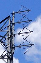 Crossed dipole FM broadcast antenna

I've noticed a few classes of antenna which (AFAIK) are missing from Wikipedia (except for the batwing antenna): TV and FM broadcasting antennas. These are widely used, but there are many specialized types which are mainly known by broadcast engineers. They consist of specialized dipole, turnstile, and reflective array antennas, with multiple antennas stacked vertically along the supporting mast to increase the gain. My question is, where do you think they should be put? I would like to have a discussion on this with any interested editors, to try to come to a consensus before adding them. Some options:
- Content on these antennas could be added to existing articles like Dipole antenna, Turnstile antenna, or Collinear antenna array
- Separate new articles could be created for each individual type: Split ring antenna
- All the broadcast antennas used for a single application could be discussed in one umbrella article: FM broadcasting antennas, Television broadcasting antennas
Talk:Alnico[edit]
- "They [Alnico alloys] are characterized by high remanence and available energy and moderately high coercivity" Laughlin, Warne, Electrical Engr's Reference Book, p.8-14
- "Permanent magnet materials are differentiated from the softer substances more particularly by their high coercivity" Heck, Magnetic Materials, p.238
- "A major breakthrough came in 1931 with the discovery of the ... high coercive field of the...aluminum-nickel-cobalt-iron alloys (Alnico alloys). With these alloys the coercive field was increased by an order of magnitude compared to the old tungsten and chromium steels" Gerber, Wright, Asti, Applied Magnetism, p.335
- "The materials for making permanent magnets...must have high coercivity. So...some alloys like Alnico and Ticonol are preferred for making permanent magnets" Tata, Physics for class XII, p.114
- "[Alnico] exhibited coercivity of over 30kA/m, which was almost double that of the best steel magnets then available. Until the development of the rare earth magnets...alnico was the main hard [high coercivity] magnetic material" Tumanski, Handbook of Magnetic Measurements, p.146
- "These [Alnico] are characterized by high remanence, high available energy and moderately high coercivity" Newne's Electric Power Engineer's Handbook, p.35
- "Hard magnetic materials are usually classified as having coercivities over 10kA/m (125 Oe), but some permanent magnet materials have coercivities two orders of magnitude greater than this. For example...56 kA/m (700 Oe) in Alnico.
For AM broadcasting[edit]
An important point that I added to article, that broadcasting was not anticipated when AM transmission was invented. This is from February 2017 version of article, and was subsequently removed.
History[edit]
The technology of amplitude modulation (AM) radio transmission was developed during the two decades from 1900 to 1920. Before this, the first radios transmitted information by wireless telegraphy, in which the radio signal did not carry audio (sound) but was switched on and off to create pulses that carried text messages in Morse code. This was used for private person-to-person communication and message traffic, such as telegrams.
With a few exceptions, the entrepreneurs who developed AM "radiotelephone" transmission did not anticipate broadcasting voice and music into people's homes.[10] The term "broadcasting", borrowed from agriculture, was coined for this new activity (by either Frank Conrad or RCA historian George Clark[10]) around 1920.[10] Prior to 1920 there was little concept that radio listeners could be a mass market for entertainment.[10] Promoters saw the practical application for AM as similar to the existing communication technologies of wireless telegraphy, telephone, and telegraph: two-way person-to-person commercial voice service, a wireless version of the telephone.[11] There were a number of experimental broadcasts during this period, these were mostly to provide publicity for the inventor's products. True radio broadcasting didn't begin until around 1920, when it sprang up spontaneously among amateur stations. AM remained the dominant method of broadcasting for the next 30 years, a period called the "Golden Age of Radio", until FM broadcasting started to become widespread in the 1950s. AM remains a popular, profitable entertainment medium today and the dominant form of broadcasting in some countries such as Australia and Japan.
For Gridiron pendulum[edit]
Condition for compensation[edit]
The length of the rods needed for temperature compensation can be calculated from the coefficients of thermal expansion (CTE) of the two metals used. Consider a zinc-steel pendulum which has two iron rods and one zinc rod. The total length of the pendulum from pivot to bob equals the length of the two iron rods and minus the length of the zinc rod


The change in length of the pendulum due to a change in temperature is equal to the thermal expansion of the two iron rods , minus the thermal expansion of the zinc rod , since the zinc rod lifts the bob up. For the pendulum to stay the same length this must be equal to zero


The coefficient of thermal expansion is the fractional change in length of the metal with a temperature change of one degree. So the thermal expansion of each rod is equal to the coefficient of thermal expansion of the metal times the length of the rod times the change in temperature. If is the CTE of iron and is the CTE of zinc


Substituting into (1)

Simplifying, for temperature compensation the length of the rods must satisfy

That is, the ratio of the total length of the two iron rods to the length of the zinc rod must equal the inverse ratio of the temperature coefficients. The total length of the pendulum must be

For Cathode[edit]
Charge flow[edit]
The terms anode and cathode are not defined by the voltage polarity of electrodes but the direction of current through the electrode. A cathode is an electrode through which conventional current (positive charge) flows out of the device to the external circuit (or electrons flow into the device), while an anode is an electrode through which conventional current flows into the device (electrons flow out of the device). Positive charge carriers, for example the positively charged cations in an electrochemical cell, always move through the device to the cathode, while negative charge carriers, such as negatively charged anions in a cell, move through the device towards the anode.
The electrodes' names are based on the direction of current flow, so the terminal through which positive charge flows out of the device (electrons flow into the device) is always called the cathode, but the polarity (voltage) of the cathode with respect to the anode can be positive or negative depending on the device and how it is being operated
Electrical loads: electrolytic cell, recharging battery[edit]

- In a polarized electrical load, a device which is absorbing electrical energy from the external circuit, such as a recharging battery cell, the cathode has a negative voltage with respect to the anode
- In the external circuit, conventional current is forced to flow out of the negative cathode through the circuit and into the positive anode (electrons flow out of the anode and into the cathode) in the direction of increasing potential energy. A source of power is required in the external circuit to make the charge carriers move in this direction, against the force of the electric field. In a recharging battery this is provided by the battery charger, which gets power from the mains.
- Inside the device, conventional current flows from the positive anode to the negative cathode, in the direction of lower potential energy. The charge carriers lose potential energy, which is converted to some other type of energy in the device, for example chemical energy in the recharging battery. In an electrochemical cell of this type, called an electrolytic cell, the reduction reaction occurs at the cathode, while the oxidation reaction occurs at the anode.
Power source: voltaic cell, discharging battery[edit]
- In a polarized power source, a device which is producing electrical energy, such as a battery powering a flashlight, the cathode has a positive voltage with respect to the anode
- In the external circuit, conventional current flows out of the positive cathode and into the negative anode (electrons flow out of the anode and into the cathode) in the direction of lower potential energy.[12] The electrons lose potential energy, which is consumed in the circuit. In the example of the flashlight the electrical energy is converted to light energy in the light bulb.
- Inside the device, conventional current flows through the device from the negative anode to the positive cathode, in the direction of higher potential energy. The charge carriers gain potential energy which flows into the external circuit. To force the charge carriers to move in this direction, against the force of the electric field, requires a source of energy in the device. In the battery, this is the chemical energy stored in the reactants. In an electrochemical cell of this type, called a voltaic cell, the oxidation reaction occurs at the cathode. while the reduction reaction occurs at the anode.
It can be seen that in devices in which the direction of current can change, such as a rechargeable battery, the names of the terminals change depending on which direction the current is flowing. In an electrochemical cell the polarity of the electrodes does not change with current direction; one terminal is always positive and the other one negative. The positive terminal is called the cathode when the cell is providing power, but the anode when the cell is being recharged.
Diodes[edit]
In semiconductor diodes and vacuum tubes the names of the terminals don't change, they are always based on forward direction of current though the device, although semiconductor diodes can conduct some current in the "reverse" direction. The terminal through which conventional current leaves the diode or tube (electrons enter the diode) when it is forward biased, is called the cathode, while the terminal through which conventional current enters (electrons leave) when it is forward biased is called the anode. In many diodes the cathode end of the device is labelled with a colored ring.
(original text)[edit]
although cathode polarity depends on the device type, and can even vary according to the operating mode. , and in a device which provides energy (such as battery in use), the cathode is positive (electrons flow into it and charge flows out): A battery or galvanic cell in use has a cathode that is the positive terminal since that is where the current flows out of the device. This outward current is carried internally by positive ions moving from the electrolyte to the positive cathode (chemical energy is responsible for this "uphill" motion). It is continued externally by electrons moving into the battery which constitutes positive current flowing outwards. For example, the Daniell galvanic cell's copper electrode is the positive terminal and the cathode. A battery that is recharging or an electrolytic cell performing electrolysis has its cathode as the negative terminal, from which current exits the device and returns to the external generator as charge enters the battery/ cell. For example, reversing the current direction in a Daniell galvanic cell converts it into an electrolytic cell[13] where the copper electrode is the positive terminal and also the anode. In a diode, the cathode is the negative terminal at the pointed end of the arrow symbol, where current flows out of the device. Note: electrode naming for diodes is always based on the direction of the forward current (that of the arrow, in which the current flows "most easily"), even for types such as Zener diodes or solar cells where the current of interest is the reverse current. In vacuum tubes (including cathode ray tubes) it is the negative terminal where electrons enter the device from the external circuit and proceed into the tube's near-vacuum, constituting a positive current flowing out of the device.
- ^ Nahin, Paul J. (2001). The Science of Radio: With Matlab and Electronics Workbench Demonstration, 2nd Ed. Springer Science & Business Media. pp. 45–48. ISBN 978-0387951508.
- ^ a b Coe, Lewis (2006). Wireless Radio: A History. McFarland. pp. 3–8. ISBN 978-0786426621.
- ^ McNicol, Donald (1946). Radio's Conquest of Space. Murray Hill Books. pp. 57–68.
- ^ Cite error: The named reference
Leewas invoked but never defined (see the help page). - ^ a b c d e Phillips, Vivian J. (1980). Early Radio Wave Detectors. London: Inst. of Electrical Engineers. pp. 18–21. ISBN 978-0906048245.
- ^ a b Phillips, Vivian J. (1980). Early Radio Wave Detectors. London: Inst. of Electrical Engineers. pp. 205–209, 212. ISBN 978-0906048245.
- ^ a b c d Cite error: The named reference
Lee1was invoked but never defined (see the help page). - ^ Cite error: The named reference
Braunwas invoked but never defined (see the help page). - ^ Cite error: The named reference
Sterlingwas invoked but never defined (see the help page). - ^ a b c d Greb, Gordon; Adams, Mike (2003). Charles Herrold, Inventor of Radio Broadcasting. McFarland. pp. 220–221. ISBN 0786483598.
- ^ "Lee De Forest as Early Radio Broadcaster" on De Forest.com website excerpted from Adams, Mike (1996). "The Race for the Radiotelephone:1900-1920". The AWA Review. 10. Antique Wireless Association: 78–119.
- ^ FAQ, Duracell website
- ^ [1] Archived 4 June 2011 at the Wayback Machine, Daniell cell can be reversed to, technically, produce an electrolytic cell.
For Talk:Radio receiver[edit]
86.162.147.159, good references. Yes, the mechanism of action of the Audion was really not "lost to history". "Soft" (incompletely evacuated) triodes, descendents of the Audion, were used throughout the 20s as detectors, and their differences from "hard" triodes are thoroughly described in electronics books. After becoming obsolete as detectors they spawned a line of "gas filled triodes" such as thyratrons used for switching. Here are some more references:
- Tyne, Gerald "The Saga of the Vacuum Tube", part 9, Radio News, December 1943, p.30 Detailed history of invention of vacuum tubes serialized in radio magazine. This part describes invention of the Audion.
- Tyne, "The Saga of the Vacuum Tube", part 6, Radio News, Sept 1943, p. 26 More on different types of Audion.
- McNicol, Don "Radio's Conquest of Space", Murray Hill Books, 1946 (p.168) "...There was a general recognition of two distinct actions in the tube depending on whether the tube was highly exhausted or contained appreciable gas." (p.180) Armstrong's Dec 1914 IRE paper explaining that there were two ways the Audion could rectify: "...one depending on the form of the nonlinear operating characteristic of the Audion and the other depending on the so-called valve action...[due to cutoff of the tube]"
It wasn't so much the long-term absorption of gas by the tube walls, as in cold-cathode x-ray tubes, which caused the variation in Audion characteristics (Audions only had a lifetime of about 50 hours). It was the outgassing of absorbed gas by the metal parts in the tube as they heated up during operation, as described in the article. Audions were "bright emitter" tubes; they didn't have an alkaline earth coating on the filament like later tubes to reduce the work function, so to get adequate electron emission the filament had to be heated white hot, increasing operating temperature. One of Langmuir's innovations was to make the plate out of a fine wire mesh, reducing the metal surface area in the tube and thus the released gas.
I agree with Gah. I appreciate your experience, but some of your statements above are clearly wrong:
"The audion... was not an amplifying device in its own right."
It was not a good amplifier, for the reasons given above, but it was an amplifier, the first practical one. The reason the big corporate labs started research programs on the audion - Arnold in 1912 at AT&T and Langmuir in 1913 at GE- was it's audio amplifying ability, which was used to make the first telephone repeaters, not its radio detection ability:
- Felix Lowenstein got the audion to work as an amplifier in 1911 by adding the C bias battery in the grid circuit. He had demonstrated some amplification in 1909 and 1910 but "... on 13 November 1911 he reported success." Lowenstein's drawings "...clearly show a grid audion provided with input and output transformers connected as an amplifier in the receiving leg of a standard telephone instrument." This was a "soft" (gassy) tube, not a hard vacuum tube. Aitken "The Continuous Wave: Technology and American Radio", p.228, Hong, p.182
- Edwin Armstrong in his paper "Some recent developments in the Audion receiver" read December 1914 at the IRE, clearly described how the audion could both rectify and amplify. For rectification the tube is biased on the curved portion of the Vg/Ip characteristic near cutoff, while for amplification it is biased on the straighter section above. In the "soft" audion due to ionization the graph is more curved, which may cause some distortion, and steeper, and the plate voltage has to be kept below the voltage at which breakdown ("blue glow") occurs, limiting output, but it clearly amplifies.

- De Forest built a 3 stage audion audio amplifier in 1914, described in Lee De Forest (March 1914) The Audion - Detector and Amplifier in Proc. of the Institute of Radio Engineers, Institute of Radio Engineers, NY, Vol. 2, No. 1, p.23, fig. 5 . He also sold an audion amplifier, the PJ-5 Douglas, p.163
- "De Forest's patented "triode" or "audion" tube could both rectify and amplify..." Lee De Forest, Inventor Archive, Lemelson-MIT Education website
- "Beginning in the early 1910s, de Forest’s audion (or triode) was used not only as a rectifier but also as an amplifier and as an oscillator. Hong 2001 "Wireless: From Marconi's black box to the Audion", p.119
- "1906: De Forest invented the three-electrode valve or vacuum tube triode. The original device was known as the Audion valve. [...] He found that when a microphone transformer was connected between the grid and the filament of the audion valve, the sound in the earpiece was much louder than when the earpiece was connected across the transformer (i.e., his discovery represents the first use of the three electrode valve as an amplifier)" Sarkar, Mailloux, Oliner "History of Wireless", p.100
Of course the hard vacuum tubes were better amplifiers, and triode development split into two lines: "hard" triodes which were used as amplifiers, and "soft" triodes which were used as radio detectors through the 1920s. MacNicol, p.

"You couldn't even buy an audion on its own. It could only be bought as part of De Forest's RJ6 receiver..."
No, De Forest sold an audion "detector", the RJ-5, consisting of the tube mounted on a box with some biasing components. Beginning at least 1914 he also sold an audion amplifier, the PJ-1. Douglas, "Radio Manufacturers of the 1920s", p.163
"...the differences between the audion and the true high vacuum triode have been lost to history."
Virtually all quality histories of electronics and of wireless describe the drawbacks of De Forest's original incompletely evacuated audion, which were corrected by the development of hard vacuum tubes. The audion-type "soft" triodes were used throughout the 1920s as detectors, so electronic textbooks of the time described the different operating characteristics of "soft" and "hard" triodes. The line of "gas-filled triodes" continued with thyratrons, that were used for switching up until the 1970s, so the operation of gas triodes is thoroughly understood and described in technical literature.
For Radio[edit]
History[edit]
Electromagnetic waves were predicted by James Clerk Maxwell in his 1873 theory of electromagnetism, now called Maxwell's equations; he proved that a coupled oscillating electric field and magnetic field could travel through space as a wave,[1] and proposed that light consisted of electromagnetic waves of short wavelength. On November 11, 1886, German physicist Heinrich Hertz, attempting to confirm Maxwell's theory, first observed radio waves, electromagnetic waves of longer wavelength than light, which he generated using a spark excited dipole antenna.[2] Experiments by Hertz showed that radio waves like light demonstrated reflection, refraction, diffraction, polarization, standing waves, and traveled at the same speed as light, confirming that both light and radio waves were electromagnetic waves, differing only in frequency.[3] In 1896, Guglielmo Marconi developed the first radio communication systems, using a spark gap transmitter and coherer receiver to send Morse code over long distances.[1] By December 1901, he had transmitted across the Atlantic ocean. Radio, then called wireless telegraphy, began to be used commercially around 1900.
During radio's first two decades, 1900 to 1920, primitive spark radio transmitters were mainly used, which could only transmit pulses of radio waves (damped waves), not the continuous waves which were needed for audio modulation. So these radio systems could not transmit sound, and instead communicated by radiotelegraphy; the sending operator tapped on a switch called a telegraph key, turning the transmitter on and off to create pulses of radio waves encoding text by Morse code.[1] Radiotelegraphy was used for long distance person-to-person commercial, diplomatic and military text messaging through the first half of the 20th century. Starting around 1908 industrial countries built worldwide networks of powerful transoceanic transmitters to exchange telegram traffic between continents and communicate with their colonies and naval fleets.[4]: p.269-272
The first continuous wave transmitters, the Poulsen arc converter and Alexanderson alternator, as well as rectifying electrolytic and crystal radio receiver detectors enabled the development of amplitude modulation (AM) radiotelephony around 1904 - 1915 by Reginald Fessenden, Lee De Forest and others, allowing sound (audio) to be transmitted.[4]: p.274-278 [1] All these early technologies were superseded by the amplifying triode vacuum tube developed 1907 - 1914 by Lee De Forest, which revolutionized radio. Vacuum tube feedback oscillators were much cheaper radio wave sources and could be easily modulated. On November 2, 1920, the first commercial radio broadcast was transmitted by radio station KDKA in Pittsburgh, owned by Westinghouse Electric and Manufacturing Company in Pittsburgh, featuring live coverage of the Harding-Cox presidential election.[1][5]
AM radio broadcasting was the first electronic entertainment medium and became explosively popular in the 1920s, introducing the public to radio. Wideband frequency modulation (FM) developed by Edwin Armstrong in 1936[1] had higher fidelity than AM, so FM broadcasting which began in 1938 was used for serious music. Experimental mechanical scan television broadcasts were made beginning with John Logie Baird's 25 March 1925 London demonstration, but did not achieve sufficient resolution to become popular until the development of electronic scan television in the 1930s.[1] Television broadcasting which began in the late 1930s replaced radio broadcasting as the most popular electronic entertainment medium in the 1950s.
The first powerful sources of microwaves, the klystron and cavity magnetron tubes, were invented just prior to World War II for use in military radar. After the war the microwave bands were exploited commercially, starting with microwave relay networks in the 1950s and communication satellites in the 1960s.[1]
- ^ a b c d e f g h Otung, Ifiok (2021). Communication Engineering Principles. John Wiley. pp. 18–19. ISBN 9781119273967.
- ^ "125 Years Discovery of Electromagnetic Waves". Karlsruhe Institute of Technology. May 16, 2022. Archived from the original on July 14, 2022. Retrieved July 14, 2022.
- ^ Sungook Hong, Wireless: From Marconi's Black-box to the Audion, MIT Press, 2001, pages 5-10
- ^ a b Huurdeman, Anton A. (2003). The Worldwide History of Telecommunications. John Wiley and Sons. ISBN 978-0471205050.
- ^ Cite error: The named reference
History of Commercial Radiowas invoked but never defined (see the help page).
For Talk:Quantum mechanics[edit]
- John Bell himself coined the term superdeterminism, and discussed it as an alternative possible explanation for failure of the Bell inequality, in addition to nonlocality. It seems to have become popular recently. As shown above, it's in the textbooks. If you say you only want to include in the article what has "actually been discovered" about QM, nonlocality has of course not been proven. The nonlocality conjecture is on an equal basis with superdeterminism and several other less likely "conjectures" to explain the Bell result; there is no experimental evidence for choosing between them. The only reason for preferring nonlocality is that instantaneous faster-than-light correlations between wavefunctions seemed to some more likely than the weird violation of statistical independence required by superdeterminism.
- You are undoubtedly right that nonlocality is a more widely known and accepted theory, but it's not yet "at the basis" of QM.