
Wikipedia:Reference desk/Archives/Science/2016 November 5
| Science desk | ||
|---|---|---|
| < November 4 | << Oct | November | Dec >> | November 6 > |
| Welcome to the Wikipedia Science Reference Desk Archives |
|---|
| The page you are currently viewing is an archive page. While you can leave answers for any questions shown below, please ask new questions on one of the current reference desk pages. |
November 5[edit]
Protrusions in lower jaw?[edit]
Recently I was at the dentist getting a cleaning, and the technician mention that I have a somewhat uncommon feature just behind my lower front teeth (on either side, underneath the tongue), which I understand to be bone protrusions, just underneath the gum, that are like two little bumps in the gum in that area (almost like two recessed lower "fangs" that have not formed). She only mentioned it because she was having difficulty positioning the mouthpiece for the x-ray. I didn't really follow up with her about it (it seemed of no concern, and because, you know, at the dentist it's somewhat hard to have a conversation), but I wonder if someone could provide the name of this dental feature so that I can get more info, just out of curiosity. Thanks! Ditch ∝ 00:54, 5 November 2016 (UTC)
- Doesn't sound like a bone spur (osteophyte) or enthesophyte. StuRat (talk) 01:03, 5 November 2016 (UTC)
- No, I don't think so. From the context of our conversation, it seemed like a "normal" dental trait, just not one she sees a whole lot. She had a clinical name for it. I just can't remember. Ditch ∝ 01:06, 5 November 2016 (UTC)
- Wait, I think I found it: Bilateral Mandibular Tori. We have an article, somewhat less specific than what I have, but basically the same thing Torus mandibularis. Seems like I grind my teeth too much, which is unfortunately true. Ditch ∝ 01:17, 5 November 2016 (UTC)
- What, that's a medical condition? I thought everyone had them...(edit) Looking at some better images on Google than are in our article, looks like quite a variety of shapes and sizes can occur. Someguy1221 (talk) 02:30, 5 November 2016 (UTC)
- Wait, I think I found it: Bilateral Mandibular Tori. We have an article, somewhat less specific than what I have, but basically the same thing Torus mandibularis. Seems like I grind my teeth too much, which is unfortunately true. Ditch ∝ 01:17, 5 November 2016 (UTC)
- No, I don't think so. From the context of our conversation, it seemed like a "normal" dental trait, just not one she sees a whole lot. She had a clinical name for it. I just can't remember. Ditch ∝ 01:06, 5 November 2016 (UTC)
Manganese Poisoning[edit]
How much Hemp Milk would you have to drink for Manganese poisoning? JoshMuirWikipedia (talk) 04:48, 5 November 2016 (UTC)
- This nutrition information for Hemp Milk does not indicate any manganese. This site indicates some manganese in whole hemp seeds, but I cannot see that any significant amount of manganese in the hemp milk. If you know how much manganese is in the hemp milk you are drinking, you can find information on the LD-50 of manganese from an Materials Safety Data Sheet. --Jayron32 04:53, 5 November 2016 (UTC)
- This source suggests that 200mg/kg per day of manganese dissolved within food may decrease rodent lifespan. Studies disagree on how toxic oral manganese is, and means of manganese consumption may influence the results, but let's just stick with this value. According to this, hemp seeds have 10mg of manganese per 100g of seeds. And according to Hemp milk, the are at least 8 grams of hemp seed extract in every 100grams of hemp milk. Now we have everything we need to make an educated guess. The average adult human male is 70 kilograms, so it will take chronic consumption of 14 grams of manganese per day to have some problems. That's 1,400,000 grams of seeds a day, or 17.5 million grams of hemp milk, or over 4000 gallons of hemp milk, every day. Someguy1221 (talk) 08:28, 5 November 2016 (UTC)
Is it possible to control heart rate directly as we can control our breathing?[edit]
Iv'e heard a professor who said that it's possible to control heart rate directly, by control some part of the brain, and the results are that if we put the stethoscope on the chest we don't listen any voices as it should in normal heart which beats. Is that true? and Generally is that possible to control heart rate directly? 93.126.88.30 (talk) 09:17, 5 November 2016 (UTC)
- See Biofeedback. Rojomoke (talk) 11:05, 5 November 2016 (UTC)
- In spite of some things you might read, it is not possible to alter your heart rate by simply willing it to change. There is however an inhibitory pathway from the brain to the heart, traveling through the vagus nerve, and its activity is affected by emotion. In other words, you can alter your heart rate to a degree by thinking about things that alter your emotional state. Looie496 (talk) 14:52, 5 November 2016 (UTC)
- Our Freediving article states "Before competition attempt, freedivers perform preparation sequence, which usually consists of physical stretching, mental exercise and breath exercise. It may include sequention of variable length static apnea, special purging deep breaths, hyperventilation. Result of preparation sequence is slower metabolism, lower heart rate and breath rate, lower level of CO2 in bloodstream"(my bold). DrChrissy (talk) 20:45, 5 November 2016 (UTC)
- Indeed, see also here. Count Iblis (talk) 02:39, 7 November 2016 (UTC)
why do people get sickness and diseases in the winter more than in the summer?[edit]
First of all is that true that people get sickness in the winter more than the summer? (apparently it seems so, because of the differences at the emergency rooms in these two times) and if it is true, what is the reason for that? 93.126.88.30 (talk) 09:48, 5 November 2016 (UTC)
- One explanation I've seen suggested is that in winter people congregate together in spaces that are less well ventilated than in summer, thus providing more opportunity for transmission of communicable diseases. There may well be other factors, and perhaps someone else can provide some references. Dbfirs 12:16, 5 November 2016 (UTC)
- Common_cold#Weather mentions several possible reasons (with refs), some of which may also apply to other illnesses. The British NHS thinks that a range of diseases may be triggered by cold weather. HenryFlower 13:21, 5 November 2016 (UTC)
- Yes, this research suggests that "seasonal exposure to cold air causes an increase in the incidence of upper respiratory tract infections due to cooling of the nasal airway" and "inhalation of cold air causes cooling of the nasal epithelium, and ... this reduction in nasal temperature is sufficient to inhibit respiratory defences against infection such as mucociliary clearance and the phagocytic activity of leukocytes." Dbfirs 13:50, 5 November 2016 (UTC)
- Don't forget the health effects of low humidity, also found in winter. Chapped lips are a visible sign, and microbes can gain entry to the blood stream via any breaks in the skin like that. StuRat (talk) 15:32, 5 November 2016 (UTC)
- Yes, infectious disease is more common in winter, such as the common cold (cited by Henry) and influenza. In fact, in the US, all-cause mortality is 15-20% higher in winter than summer, due in large part to the impact of seasonal diseases on already vulnerable populations (e.g. the elderly). Dragons flight (talk) 13:58, 5 November 2016 (UTC)
Nuclear attack[edit]
If a 25-megaton atom bomb is detonated at optimal height, what would be the destructive radius based on blast effects and thermal effects? (More specifically, if detonated over the geometric center of Qatar, would it destroy everything within Qatar's borders?) Is it true that for an explosion of this size, thermal effects will dominate? 2601:646:8E01:7E0B:F88D:DE34:7772:8E5B (talk) 10:24, 5 November 2016 (UTC)
 Please do your own homework.
- Welcome to Wikipedia. Your question appears to be a homework question. I apologize if this is a misinterpretation, but it is our aim here not to do people's homework for them, but to merely aid them in doing it themselves. Letting someone else do your homework does not help you learn nearly as much as doing it yourself. Please attempt to solve the problem or answer the question yourself first. If you need help with a specific part of your homework, feel free to tell us where you are stuck and ask for help. If you need help grasping the concept of a problem, by all means let us know. Dolphin (t) 10:50, 5 November 2016 (UTC)
- This doesn't seem like a homework question, but an interesting hypothetical scenario. But looking at the article it says "If detonated at optimal height, the B-41 would generate a fireball approximately 4 miles (6.4 km) in diameter, it would have been able to destroy reinforced concrete buildings 8 miles (13 km) from ground zero, and it would have been able to destroy most residential structures 15 miles (24 km) from ground zero, while producing third degree burns 32 miles (51 km) from ground zero.", so it seems like someone's already given us a lot of this information in the article. Now... if only they had a source for that statement there we'd be in business; otherwise, we can do somebody's alleged homework and fix a sourcing problem at the same time. :) Unfortunately none of the three refs there seem to cover any of this. Actually, one issue - looking at the development schedule they do cite - is that the bomb's components apparently weren't tested above 5 MT. Since it says the 25 MT version was a "dirty" nuclear bomb with heavy fallout, this is a good thing. But it means this is a guess or a simulation with computers from 1960 by an army with a track record (e.g. Castle Bravo) of badly misestimating the yield, including a fizzle during the testing of that weapon. So I feel like this Wikipedia-induced hallucination, wherever it came from, can't possibly be relied on, though it's as good a guess as any. Our article on nuclear weapon yield gives a figure of 3.7 km for a 15 MT bomb (well, the figure shows half that, but our legend says the figure is wrong. Typical.)
- Meanwhile Qatar is 4467 square miles, and no matter how you push that around, I don't think you're going to fit it under that nuke. (Well, unless you count the fallout) But I like the direction of your mind. :) Wnt (talk) 12:25, 5 November 2016 (UTC)
- Absolutely NOT homework -- I don't think they teach about nuclear weapon effects in school (or even in college, unless it's at West Point)! 2601:646:8E01:7E0B:F88D:DE34:7772:8E5B (talk) 01:00, 6 November 2016 (UTC)
- See here for an estimation. I'm not sure I'd want to be anywhere near a school where estimating nuke effects is part of the curriculum....! Fgf10 (talk) 08:52, 6 November 2016 (UTC)
- Thanks! 2601:646:8E01:7E0B:F88D:DE34:7772:8E5B (talk) 09:07, 6 November 2016 (UTC)
- And there's also the Nuclear electromagnetic pulse. Hofhof (talk) 10:44, 8 November 2016 (UTC)
- Actually a relevant question for anyone living in a country that hosts pre-positioned US Air Force supplies and 10,000 US and British troops at Al-Udeid. It's unlikely an enemy (say, the Russians during future operational warfare in the Persian Gulf) would use a 25Mt weapon, when a 1 Mt airburst directly over Al-Udeid would likely destroy the airstrip, kill most US and British military there, and inflict only minimal damage at Doha and other cities outside a roughly 10 kilometer radius of blast center.
- While Qatar and Iran reportedly enjoy relatively close relations, relations between Saudi Arabia and Qatar deteriorated badly in 2014 (but have since recovered) and could do so again. If rumors of nuclear sharing between Saudi Arabia and Pakistan are true, Qatar may be on the Saudi nuclear target list (if one exists). Saudi Arabia has purchased two separate missiles from China capable of striking Qatar (the CSS-2 and CSS-5), both of which carry nuclear weapons in Chinese service.
- In either the 25 Mt or 1 Mt scenario, overpressure and thermal effects would account for most prompt casualties country-wide. The predominant damage mechanism for structures would vary with their construction. Stone, reinforced concrete and earthen construction would be least vulnerable, while wood frame construction and prefabricated metal structures would suffer more damage at greater distances from blast center. The Nukemap simulation results I and Fgf10 supplied ought to give you detailed estimates of which areas would be subjected to which nuclear weapon effects.
- If you choose to really put time into this, I suggest you read The Effects of Nuclear Weapons by Samuel Glasstone and Philip Dolan, the main reference cited in US Government publications which discuss nuclear weapon effects. loupgarous (talk) 01:45, 9 November 2016 (UTC)
Generating electricity from domestic water pressure[edit]
The incoming mains water to my house is 4 bar via a 15mm copper pipe. I do not have a water meter so pay a set charge no matter how much I use. If I connected the incoming water supply to some kind of contraption that turned an alternator or dynamo, how much electricity would I be able to generate? Jinpingwoo2 (talk) 15:48, 5 November 2016 (UTC)
- This Q has been asked before, and I believe the answer was that it would be too little electricity to pay for the equipment over it's projected life. If this wasn't the case, everyone would do it, and then nobody would provide unlimited water at a set charge. Also, note that you can get "free electricity" from solar panels, although it's similarly not free when you consider the cost of the equipment, amortized over the projected life. In fact, it's usually more expensive than regular electricity. StuRat (talk) 16:08, 5 November 2016 (UTC)
- We'd like to assume this is a thought problem only, i.e. the pressure doesn't drop below 4 bar when the water is running. Otherwise you may get more energy from the heatedness of your town's reaction. :) Let's see where that gets us... Then you have a pressure of four bar = 400 kPa, where 1 Pa = 1 kg m-1 s-2 = 1 J m-3 energy density. Now you have this energy density over an area of pi (0.015 m/2)^2 = 0.0001767146 m^2, so we now have a figure of oh, 70.7 J/m. Meaning what? Well, I guess for every linear meter of water in the pipe you decompress you get 70 J. But how much power is that in watts? Well, depends on how many meters you decompress every second. Which implies we *need* to know that rate of flow, which we know intuitively can't be infinite. I have no idea how to calculate it, but you could measure how many buckets you fill, and get a figure, and convert that to m^3 of water and figure it out, or somehow measure how fast the water flows for a m/s reading in the pipe. Just take 400000 J/m^3 * x m^3 = 400000 x J/s or 70 J/m * x m/s and get 70x J/s.
- Now of course, even after the water is decompressed, it might deliver more energy. You might have a cliff outside your house and you can drive a water wheel with it. Or maybe the municipal sewer is a way down and that too is unmetered... Of course, don't do this because it's mad; the city will get curious where the leak is and find it, or you'll flood your basement, or something. Wnt (talk) 16:18, 5 November 2016 (UTC)
- XKDC has already worked out the math: [ https://what-if.xkcd.com/91/ ].
- Here are some vendors who will sell you a Micro-hydro generator.[1][2][3] Enough to recharge a cellphone or maybe a laptop if you have water and no electricity.
- Here is a clever fellow who proposes extracting energy from the temperature difference between his city water and outdoors, then pumping the water back, reversing his water meter: http://www.eagle-research.com/cms/blog/free-energy/generating-electricity-using-household-water-pressure-or-heat --Guy Macon (talk) 18:07, 5 November 2016 (UTC)
- @Guy Macon: [oops, I used the wrong figure, not the wrong math the first time!] xkcd draws a pretty comic, but it's the same calculation. With the notable omission that, although they admit the flow rate is a crucial part of the calculation, they never say what it is. But since they come up with 200 watts of power, you can divide that by 400000 J/m^3 to get 200 /400000 m^3 = 50 cm^3 (ml) of water per second to produce that power (they use almost the same pressure, 4 atm instead of 4 bars and who's really measuring?). I'm getting that it takes 40 seconds to fill up a 2-liter bottle that way, which is believable for a bathroom tap; mains are probably better. Wnt (talk) 00:05, 6 November 2016 (UTC)
- Try another version: Call it a spherical cow,back of the envelope calc: my house has faucets which will each supply 3 gallons per minute. The water pressure is about 40 pounds per square inch. 3 gpm times 40 psi divided by 1714 yields .07 horsepower or 52 watts mechanical input to a generator. But my mains are engineered to furnish three baths, a laundry and a kitchen,as well as an outside hose bib implying that with a 20% pressure drop when running them all, a generator directly connected to the main might supply 18 gpm at 32 psi, or 0.33 HP or 246 watts. As a side note, some 19th century phonographs were powered from the kitchen tap via a rubber hose to a little water motor with a return hose to the sink. Edison (talk) 20:02, 5 November 2016 (UTC)
- See Hydraulic power network for our article on Edison's sidenote, incidentally. Tevildo (talk) 23:20, 5 November 2016 (UTC)
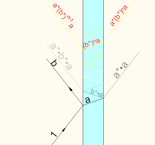
It is possible to go on with arguments of this nature and deduce that b is real. To prove this, one must consider a case where light is coming from both sides of the glass surface at the same time, a situation not easy to arrange experimentally, but fun to analyze theoretically. If we analyze this general case, we can prove that b must be real, and therefore, in fact, that b=±sin(i−r)/sin(i+r). It is even possible to determine the sign by considering the case of a very, very thin layer in which there is reflection from the front and from the back surfaces, and calculating how much light is reflected. We know how much light should be reflected by a thin layer, because we know how much current is generated, and we have even worked out the fields produced by such currents.
I want to ask again [5] . What does this part of the Lecture mean? How can we use thin layer? In thin layer refracted light beam will infinitely reflect. Second reflected beam will have amplitude , where . — Preceding unsigned comment added by Username160611000000 (talk • contribs) 18:11, 5 November 2016 (UTC)


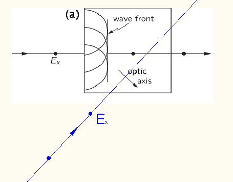
I think image (b) of Fig. 33–7 is not correct, because atoms must oscillate vertically, so secondary waves must be perpendicular to image, producing something like cylindrical surface. There is some component of the field in other directions according to formula (29.1), but it is much smaller. — Preceding unsigned comment added by Username160611000000 (talk • contribs) 18:21, 5 November 2016 (UTC)
We can split vector E into components situated only in plane perpendicular to direction of propagation (like is shown in Ch. 33–1). We cannot represent vector E as superposition of one vector perpendicular and the second vector parallel to optical axis of crystal. Is it correct? Username160611000000 (talk) 10:21, 6 November 2016 (UTC)
November 5[edit]
ID of the species[edit]
_05032016.jpg)
Can anyone help in identifying the species in the picture? Thanks in advance :). Nikhil (talk) 04:23, 10 November 2016 (UTC)
- Assam Roofed Turtle? There seem to be a lot of them in the Kaziranga National Park where this photo was taken. Richard Avery (talk) 07:55, 10 November 2016 (UTC)
- Look like it's turtles all the way down. :-) StuRat (talk) 18:19, 10 November 2016 (UTC)
It is possible to go on with arguments of this nature and deduce that b is real. To prove this, one must consider a case where light is coming from both sides of the glass surface at the same time, a situation not easy to arrange experimentally, but fun to analyze theoretically. If we analyze this general case, we can prove that b must be real, and therefore, in fact, that b=±sin(i−r)/sin(i+r). It is even possible to determine the sign by considering the case of a very, very thin layer in which there is reflection from the front and from the back surfaces, and calculating how much light is reflected. We know how much light should be reflected by a thin layer, because we know how much current is generated, and we have even worked out the fields produced by such currents.
I want to ask again [8] [9]. What does this part of the Lecture mean? How can we use thin layer? In thin layer refracted light beam will infinitely reflect. Second reflected beam will have amplitude , where . — Preceding unsigned comment added by Username160611000000 (talk • contribs) 18:11, 5 November 2016 (UTC)
- According to image png, I write next:
- Where is my mistake?
- Username160611000000 (talk) 08:27, 13 November 2016 (UTC)
- Ah, I see: ...


![{\displaystyle b^{2}[1-(a^{*})^{2}-(b^{*})^{2}]=1-(a^{*})^{2}-(b^{*})^{2};}](https://wikimedia.org/api/rest_v1/media/math/render/svg/d55b30e4fbbdab8de3cf29490e6742d7d85fb51b)


I think image (b) of Fig. 33–7 is not correct, because atoms must oscillate vertically, so secondary waves must be perpendicular to image, producing something like cylindrical surface. There is some component of the field in other directions according to formula (29.1), but it is much smaller. — Preceding unsigned comment added by Username160611000000 (talk • contribs) 18:21, 5 November 2016 (UTC)
We can split vector E into components situated only in plane perpendicular to direction of propagation (like is shown in Ch. 33–1). We cannot represent vector E as superposition of one vector perpendicular and the second vector parallel to optical axis of crystal. Is it correct? Username160611000000 (talk) 10:21, 6 November 2016 (UTC)
The diagram seems to make sense. If the E-field is perpendicular to the plane of polarization, then both components are always perpendicular to the long axis of the molecules. But if the E-field is parallel to the plane, it is still perpendicular to one of the directions within the plane while being parallel to another. The light gets some extra speed when the E-field happens to be aligned with the molecules' long axis (I'll admit, I'm a bit fuzzy on why there, but presumably that means the refractive index is lower under that circumstance). Anyway we might check out birefringence to see how Wikipedia puts it. Wnt (talk) 12:05, 11 November 2016 (UTC)
If the E-field is perpendicular to the plane of polarization
- What do you mean by plane of polarization? Plane of polarization of a polarized beam is a plane containing vector E (or in other words it's the plane of graph E vs r). How can E-field be perpendicular to the plane of polarization? Username160611000000 (talk) 16:00, 11 November 2016 (UTC)
- This was his phrase, not mine, and I suppose it did confuse me: "When this beam strikes the surface of the material, each point on the surface acts as a source of a wave which travels into the crystal with velocity $v_\perp$, the velocity of light in the crystal when the plane of polarization is normal to the optic axis" But I may have used it wrongly above. Come to think of it, I suppose he's taking the wiggle of the E-field as drawn at the left of (a) and (b), plus the forward vector of the light, to define a plane in which the light is polarized. and so it's this plane (which includes the E-field vector) which may be perpendicular to the optic axis of the crystal. The bottom line though is that when the E-field vector is in a particular direction, the light goes faster. Wnt (talk) 17:25, 11 November 2016 (UTC)
the velocity of light in the crystal when the plane of polarization is normal to the optic axis
He means that if beam would be falling like that png, then velocity would be . Username160611000000 (talk) 18:44, 11 November 2016 (UTC)- It turns out that the beam, which is falling at some angle to the optical axis (black beam on png), also has velocity . I agree with it. But I do not wholly agree with statement that secondary waves are spherical. Even if crystal would be isotropic, waves would not be spherical as intensity decreases in directions close to line of acceleration of charges. Maximum intensity will be in plane perpendicular to acceleration of a charge. In the image (a) such planes for each charge are the plane of the page. In the image (b) such planes must be perpendicular to the plane of page and we could not see circles or ellipses (they must degenerate to lines). I can't understand what do that ellipses represent . Username160611000000 (talk) 19:33, 11 November 2016 (UTC)
- That's dealt with here: When this beam strikes the surface of the material, each point on the surface acts as a source of a wave which travels into the crystal with velocity v⊥, the velocity of light in the crystal when the plane of polarization is normal to the optic axis. The wavefront is just the envelope or locus of all these little spherical waves, and this wavefront moves straight through the crystal and out the other side. The way I understand it, he is giving the rather surprising view that when light strikes the crystal, each speck of crystal scatters light out spherically in all directions. However, because all these spherical waves are the same thing emitted at the same time, they add up constructively at the wave front (the line at the end of the circles) and no where else. Well, when there is an optical axis, the spheres become ellipses (ellipsoids, I guess) because light spreading out in all directions moves faster in the direction with lower refractive index. Wnt (talk) 22:53, 11 November 2016 (UTC)
Well, when there is an optical axis, the spheres become ellipses
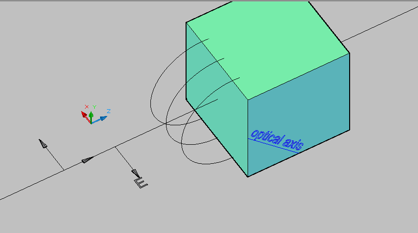
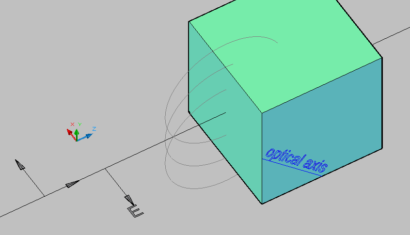
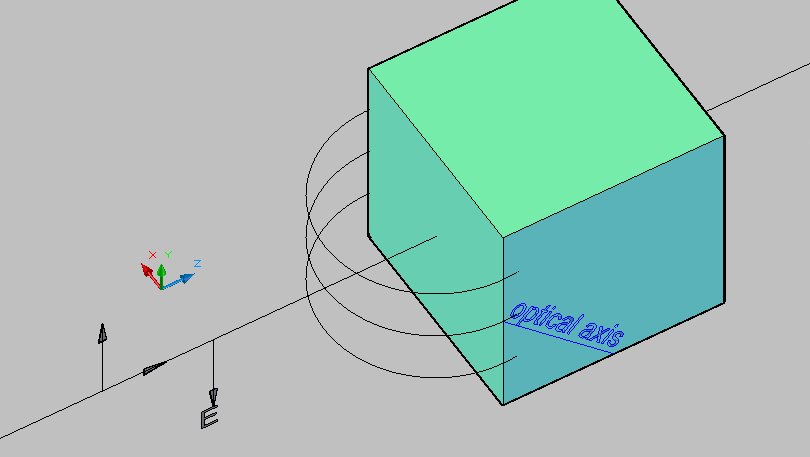
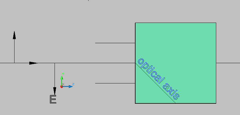
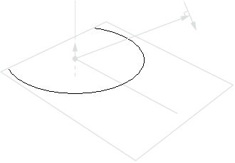
In (a) image there is also the optical axis.- Here is (a)-image in 3D png,png2, (a)-image and (b)-image are the ZY plane view. We must consider maximum intensity. So for (a)-image max. intensity waves are circles, because charges move up-down parallel to vector E, which is directed out the paper (dots on the beam). [note 1] Vector E has only one component namely Ex. Everywhere in circles vector E is also x-axis oriented (so ⊥ to the optical axis). In (b)-image the max. intensity waves are also circles, but in plane ZX, so these circles must be seen as lines in image (b).
- (b)-image in 3D: png, png. As you see, when I rotate 3D-model the circles become lines , not ellipses. Username160611000000 (talk) 07:29, 12 November 2016 (UTC)
- That's dealt with here: When this beam strikes the surface of the material, each point on the surface acts as a source of a wave which travels into the crystal with velocity v⊥, the velocity of light in the crystal when the plane of polarization is normal to the optic axis. The wavefront is just the envelope or locus of all these little spherical waves, and this wavefront moves straight through the crystal and out the other side. The way I understand it, he is giving the rather surprising view that when light strikes the crystal, each speck of crystal scatters light out spherically in all directions. However, because all these spherical waves are the same thing emitted at the same time, they add up constructively at the wave front (the line at the end of the circles) and no where else. Well, when there is an optical axis, the spheres become ellipses (ellipsoids, I guess) because light spreading out in all directions moves faster in the direction with lower refractive index. Wnt (talk) 22:53, 11 November 2016 (UTC)
- This was his phrase, not mine, and I suppose it did confuse me: "When this beam strikes the surface of the material, each point on the surface acts as a source of a wave which travels into the crystal with velocity $v_\perp$, the velocity of light in the crystal when the plane of polarization is normal to the optic axis" But I may have used it wrongly above. Come to think of it, I suppose he's taking the wiggle of the E-field as drawn at the left of (a) and (b), plus the forward vector of the light, to define a plane in which the light is polarized. and so it's this plane (which includes the E-field vector) which may be perpendicular to the optic axis of the crystal. The bottom line though is that when the E-field vector is in a particular direction, the light goes faster. Wnt (talk) 17:25, 11 November 2016 (UTC)
