
Talk:Regenerative circuit
| This is the talk page for discussing improvements to the Regenerative circuit article. This is not a forum for general discussion of the article's subject. |
Article policies
|
| Find sources: Google (books · news · scholar · free images · WP refs) · FENS · JSTOR · TWL |
| This article is rated C-class on Wikipedia's content assessment scale. It is of interest to the following WikiProjects: | ||||||||||||||||||||||||||
| ||||||||||||||||||||||||||


What a mess[edit]
The article starts "The regenerative circuit .... or "autodyne"... Unfortunately these are fundamentally different concepts. For clarity they should not be lumped together. I have edited and simplified the entry.
Likewise the Super-Regen, it's a very different concept. Should have its own page.
The line "Regenerative receiver circuits are still used in low-cost electronic equipment such as garage door openers" is utter nonsense. I think the author meant Super-Regens. These are frequently used in simple commercial products, but rarely are Regens.
Also it is a big pity that the article has such a USA bias. The "Regen" was developed and patented in a number of countries around the same time, particularly France and England who were well ahead of the USA at this time. Gutta Percha (talk) 12:53, 23 February 2014 (UTC)
- 2018 August 9 - A lot of changes have been made to the article since the above remarks were written at the beginning of 2014 by Gutta Percha. My opinion is that the article is vastly improved. Many sources have been used and cited. Further improvement could be made in organization of the article contents. I don't have any sources on which to base additions to the article at this time for development of regenerative circuits in France or England. Anyone able to contribute these, please go ahead. LSMFT (talk) 14:58, 9 August 2018 (UTC)
Communications circuit[edit]
The regenerative circuit is an electronic design for a radio receiver. The Tesla coil is a different class of device. See the article category at the bottom of the page. It belongs in a different article. Perhaps you might want to create one such as High voltage generator. --Blainster 21:59, 15 March 2006 (UTC)
Unsourced claim[edit]
In the absence of evidence for the claim: "There is some evidence to suggest that the regenerative circuit was discovered by Robert Goddard before Armstrong or De Forest. Goddard declined to apply for a patent,not wanting to endure litigation. He turned to liquid fuel rocket development." I removed it. If someone can find a reliable citation, please cite the source. Salsb 11:41, 6 September 2006 (UTC)
Join the "history" parts, please, and take out Superregenerator[edit]
I am the unlucky author of the second'history' part, i try to edit them together but some anti-vandal bot undoes my edits. May you join the history parts and make new article for Superregenerator? —The preceding unsigned comment was added by 85.140.16.243 (talk • contribs) 04:16, April 6, 2007 (UTC)
- I combined the history sections. A separate article for super-regen receivers doesn't seem necessary at this point. --Blainster 19:00, 6 April 2007 (UTC)
A super-Regen is a completely different beast. It definitely should have it's own section. This combining different concepts has made the article ridiculous. Gutta Percha (talk) 12:57, 23 February 2014 (UTC)
Concerning Description[edit]
Regenerative circuits ... must be carefully on the verge of oscillation, and in that condition, the circuit behaves chaotically. - This is not quite correct. There is a self-stabilizing effect because of the characteristics of the valve which decreases the factor with higher level of HF. -- 84.189.249.128 (talk) 14:31, 20 May 2008 (UTC)
- That whole paragraph is inaccurate, misleading and supported only by original research papers. In AM mode a regenerator applies less positive feedback than it would be needed to win over the negative feedback so nothing spectacular, chaotic or otherwise fancy happens. -- Femmina (talk) 13:53, 22 February 2011 (UTC)
I have a short book available about regenerative radio receivers that might help with this article:http://www.webstore.com/91359,owner_id,other_items It explains a lot of the technical details about how exactly regenerative radio receivers work and clears away a lot of quackery concerning their design. — Preceding unsigned comment added by 113.190.236.212 (talk) 15:07, 14 February 2012 (UTC)
Leap of logic[edit]
- Regenerative circuits use fewer components than more complex designs and because of this the regeneration level must be carefully adjusted by the user.
I don't agree with this sentence at all. It begins with a premise that is true enough - regens use fewer components, and ends in a valid observation - regens have additional controls. What I don't agree with is the logic that connects the two together - why does fewer components automatically lead to the need for additional user controls? Using this logic a crystal set would have dozens of knobs on it. CrispMuncher (talk) 13:02, 4 July 2008 (UTC)
- Well I've gone ahead and resolved the issue. It didn't need much adjustment in the end anyway. CrispMuncher (talk) 15:42, 27 August 2008 (UTC)
"Ham" is not an acronym[edit]
- "...by Russian HAM and professional operator Ernst Krenkel"
Ham is not an acronym, and shouldn't be in all caps. I didn't edit it, because the phrase "ham and professional operator" seems a little odd. How about just "radio operator"? —Preceding unsigned comment added by Thbusch (talk • contribs) 14:07, 27 August 2008 (UTC)
- I agree, not just regarding the capitalisation, "ham and professional" is a contradiction. However personally I'd be in favour of snipping the entire paragraph. It is totally unsourced, has no reference to which expedition is referred to (the article on Byrd and the List of Antarctic Expeditions do not help) and lacks even a date, which given that the record no longer holds (which now must surely go to Pioneer 10) is a major shortcoming. If no one comes forward with any comments I'll snip it in the next couple of days. CrispMuncher (talk) 15:24, 27 August 2008 (UTC)
Mains radios?[edit]
"At the time the regenerative receiver was introduced, vacuum tubes were expensive and consumed lots of power, with the added expense and encumbrance of heavy batteries or AC transformer and rectifier"
I don't think this is realistic. When reaction was introduced, valves were direct heated, thus required very clean dc for heating, otherwise overwhelming interference would have occurred. This simply could not be obtained from ac mains by any practical means. Hence radios were operated from lead acid batteries, or less often dry cells.
To clarify, the only contenders for filament power rectification were eletrolytic rectifiers and vibrating rectifiers. The stone jar electrolytic rectifiers were large, heavy, filled with liquid chemical and didnt last. Vibrating rectifiers produced so much hash as to make reception impossible. Practical capacitors at the time were of too small a capacity to act as reservoir caps, or to be able to clean up LT & HT (A & B) power lines to any significant extent. Tabby (talk) 00:16, 15 February 2012 (UTC)
- Somewhat late I know, but a couple of years ago, I stripped an AC radio down for museum piece type parts. The valves were indirectly heated (from 4 volts AC which was typical of a UK radio of pre-war vintage). The presence of a control labelled 'reaction' gave this away as a regenerative circuit. DieSwartzPunkt (talk) 17:35, 10 June 2014 (UTC)
Super-regenerative receivers[edit]
I have never met anyone who has built a super-regen receiver to listen to MW or LW AM radio signals. Is it because the distortion is bad and music and speech is intolerable on it? I have searched and searched, all to no avail. Unless I hear here from some wise enthusiast soon, I will be compelled to make one up and then post my own opinions about it here. 87.115.171.241 (talk) 20:16, 5 February 2013 (UTC)
- WP is not a place to publish original research. I would not expect people to build super-regen receivers now because other, better, receivers are simple to build and not very expensive. Glrx (talk) 03:05, 6 February 2013 (UTC)
The reasons Super-Regens are not used on BC is that they need an ultrasonic quench circuit which would generate spurious signals across the BC band. Plus because of the quench action they are very broad, with very poor Selectivity. For all these reasons they are only used on VHF and UHF. All this is well documented in the literature Gutta Percha (talk) 13:04, 23 February 2014 (UTC)
Images might mislead some people[edit]


These two images of a beutifull tube radio appear in the lead of the article. Based on the metadata I take it they are modern color images that have been converted to black and white (sepia) to make them appear older. While I appreciate the artistic effect I think it is a bit unencyclopedic and might mislead someone to think these are actually old photographs. It is not entirely clear to me if it is an old radio or a modern replica either. Perhaps someone who knows could clarify in the text and/or use the original "unmodified" images. 85.230.137.182 (talk) 17:29, 14 July 2013 (UTC)
- These are certainly not vintage radios. Although most of the component parts are typical of vintage era radio sets (though the valve looks to be a later type), the one give away is that they are wired using circular cross section wire. Wire from the same period had a square cross section because the technique of drawing circular wire had yet to be invented. Also the tin coating on the wire would be substantially oxidised after nearly 90 years, not to mention the soldered joints. I B Wright (talk) 17:24, 9 March 2014 (UTC)
- Do you have a source for the square wire claim? I've never heard of that. I would think it would be easier to make circular cross section wire. --ChetvornoTALK 18:46, 9 March 2014 (UTC)
- Even if the radio were a real vintage, the apparent date of the radio is 1930s to 40s, by which time regenerative sets were superseded by superheterodynes. So the picture isn't really representative of the "regenerative era". The article needs some pictures of 1920s sets. --ChetvornoTALK 18:46, 9 March 2014 (UTC)
Name[edit]
These were normally called reaction sets in the UK, yet this term has been removed from the article at some point. It should be there 82.31.66.207 (talk) 16:12, 30 March 2014 (UTC)
- I am from the UK and I have never heard this type of circuit referred to as a 'reaction' type receiver. They are only ever called 'regenerative' receivers as far as I am aware. Is it possible that you are getting confused because the front panel control that varied the feedback was often labelled 'reaction'? DieSwartzPunkt (talk) 17:30, 10 June 2014 (UTC)
Antenna coupling selectivity enhancement[edit]
I agree, from practical experience that M is usually around 30 to 40 in a regenerative receive. I observe that in terms of gain and narrowing of bandwidth. However that does not explain the overall selectivity I see. Particularly in terms of rejection of strong signal say 20 or 30 Khz away at say a receive frequency of 10 Mhz. I would say the parallel resonance frequency of the LC circuit is boosted up by M too. From say 20 KOhms to 800 KOhms. Such a high input impedance allows a very weak antenna coupling to nevertheless effectively transfer energy. However just off the resonant frequency the LC circuit has a much lower impedance resulting in very poor transfer of energy. I would suggest this is an additional source of selectivity in regenerative receivers. — Preceding unsigned comment added by 113.178.36.103 (talk • contribs) 02:32, 7 April 2016
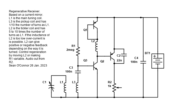
Well when the regenerative radio is oscillating it is working as a direct conversion receiver, when it is just oscillating you still get a Q boost from regeneration as well. That could explain the extra selectivity. A signal 30 KHz away will be frequency shifted out of audible range by direct conversion. What you say about the effective LC impedance being boosted to 800kOhms is also likely true. I suppose you could test that by putting a few hundred kOhm resistor across the LC circuit and seeing what effect that has. Anyway there is this circuit here if you want to try: https://ia601605.us.archive.org/24/items/current-mirror-regen/CurrentMirrorRegen.png — Preceding unsigned comment added by 14.162.199.53 (talk) 06:15, 1 February 2023 (UTC)
Block diagram[edit]

Glrx, what was your problem with the block diagram? How is it "misleading"? --ChetvornoTALK 01:58, 17 May 2016 (UTC)
- This section is about my 28 January edit] that removed thumb with the caption "Block diagram of regenerative receiver".
- There's a lot going on in a regen detector. The block diagram makes it look like either (1) a linear circuit that does not explain the detection or (2) a circuit with audio fed back to the RF input.
- RF feedback must be before detection rather than after detection. The label for block A is misleading; the implication is the output of A is detected audio rather than the RF needed to achieve selectivity.
- A regenerative amplifier can be viewed as a linear circuit because no detection is sought.
- A regenerative detector has two functions. One is the quasi-linear regenerative RF amplifier; the second is the nonlinear AF detector. The output signal of block A has both components: the RF signal and the detected signal. The diagram hides the demultiplexing of those outputs. The bandpass selects the RF component for the regen amp. The diagram does not show the lowpass filter that selects the AF for the speaker (C4 in the tube diagram).
- Glrx (talk) 17:09, 17 May 2016 (UTC)
- The bandpass filter (the input tuned circuit) which as you say selects the RF for feedback is inside the feedback loop, this should make it clear that feedback cannot occur at audio frequencies. But I see your point about the letter A. It's not supposed to stand for "audio" of course, it is the standard variable used for gain of an amplifier, just as β is the attenuation factor of the feedback loop. I was going to add the equation for the closed-loop gain of the receiver to the article. But the letters might be misleading for readers; I guess I could remove them.
- On the subject of the arrangement of blocks, I don't see that other ways are clearly better. The diagram represents the way actual circuits like the ones shown in the article are organized; the amplifier inside the loop acts as detector. Explaining the circuit as similar to a linear feedback RF amplifier followed by a separate detector might be a good approach in the text, but showing a separate detector in the diagram after the feedback loop will just be confusing to readers. Many readers don't read the text, they look at the diagrams. They will compare the block diagram to the Armstrong circuit shown next to it and not find a detector, and it will have to be explained that, no, actual circuits don't have a separate detector. I can't find any sources that depict the block diagram of a regen in that way. Also the detection and RF amplification functions of the amplifier don't separate cleanly as in your explanation; for example the cutoff of the tube needed for rectification affects its gain as an RF amplifier. Yes, a lot is going on in the regen detector, and it should be explained in the text, not simplified away in the diagram. --ChetvornoTALK 21:30, 17 May 2016 (UTC)
- I never considered that A would be interpreted as audio; all A suggests to me is a scalar linear gain. The implication of audio comes from the output of the amplifier drives an audio speaker and the use of "detector". The diagram should have a LPF to remove the RF; that LPF exists in regen detectors.
- Actual circuits are not block diagrams. A regen amp is clear; regen amps are followed by detectors but the cascade is not a regen detector. A regen det is a reflex circuit.
- The detector does not depend on tube cutoff for rectification. It is much more subtle. Typical regen detectors used either grid leak or plate detection. (Terman 1943, p. 574.) Grid leak is a rectifier that depends not on cutoff but rather the leak from forward biasing the grid wrt the cathode. The plate detector is a square law detector that depends on a non-linear transfer function; the tube need never enter cutoff.
- There is a clean separation of ideas, but there is interaction between the two.
- A better block diagram would be a regen amp followed by a diode envelope detector or a square law detector. That conveys the processing involved.
- Alternatively, the nonlinear gain block should have two outputs rather than looking like a linear amp: RF and AF.
- BTW, regen detectors were out by 1943. (Ibid.)
- Glrx (talk) 01:32, 18 May 2016 (UTC)
Tesla[edit]
IP added the statement:
- Nikola Tesla described in 1899 a telegraphic "self-exciting" receiver, on a feedback principle.
I went looking for sources and found
I don't see these references as being clear on the topic. There are claims of negative resistance and RF bias, but also of the coherer transitioning from 1 megohm to 50 ohms. I'm tempted to revert. Glrx (talk) 21:17, 23 December 2016 (UTC)
- I support a revert. The Corum paper is interesting, but I've never heard that coherers had negative resistance; if true I think it would have been noticed at the time. The Corum brothers have published a lot of other fringy claims about Tesla that are not supported by any other researchers (for example, they also claim Tesla's Colorado Springs apparatus produced Zenneck waves). Peterson's article is not a WP:RS and is just wrong: Regenerative receivers don't work by increasing the "effective area" of the antenna. Gary Peterson owns a bookstore and website specializing in New Age pseudoscience and has waged a 5 year edit battle to insert inadequately-sourced "alternative" Tesla ideas into Wireless power. The bottom line is, the new content is supported by a single dubious research paper (Corum's) and that is not enough; WP articles require WP:primary sources to be backed up by secondary sources (WP:PSTS). --ChetvornoTALK 04:57, 24 December 2016 (UTC)
The traditional Coherer reduced its Resistance in the presence of RF, and thus rang a bell. But the "Coherer" was also used in other modes. For instance Marconi's first trans-Atlantic tests were done using a Earpiece in series with a Coherer. This mode relies on the Coherer acting as a "dirty contact detector", eg similar to a cat's whisker. There were also frequent reports of a carefully biased Coherer becoming super-sensitive. Today this is understood as entering the Negative resistance mode.
Most dissimilar metal junctions will operate as a Detector when carefully adjusted (pressure and/or bias), and also can be coaxed into negative resistance. The classic Coherer is no different. Gutta Percha (talk) 23:32, 28 October 2018 (UTC)
Clandestine receivers[edit]
In about 2007 I was part of this exchange in the "talk" on Crystal recievers:
Can somebody familiar with classic sets and recent experimentation
comment on the range of frequencies/wavelengths which this type of
receiver is effective with? I note elsewhere reference to around 300m
and there's an old story (possibly apocryphal) of picking up 2LO
[350m] with a coil of wire wrapped around your hand and a bit of coal
:-)

Noting that Russia has just booted out the BBC there could be a
revival of interest in simple receivers as an alternative to
Internet-distributed news which is too easy to monitor or block.
MarkMLl 10:39, 18 August 2007 (UTC)

    We here build regenerative radios ;)) There are two circuits for
FET and BJT respectively, we call it "three-pointie" ("трёхточка",
"trehtochka" in Russian) - almost nothing is needed beyond a
throttling pot, transistor, LC and 1,5V cell. —Preceding unsigned
comment added by 85.140.16.75 (talk) 19:53, 9 September 2007 (UTC)
Is anybody familiar with the трёхточка/trehtochka as a minimal (possibly clandestine) receiver, and if so would it merit a section in the article? MarkMLl (talk) 08:05, 16 October 2019 (UTC)
- Is this type of receiver really a regenerative receiver? Does the transistor have a feedback circuit? From your description it sounds more like a simple TRF receiver with a single transistor amplifier. --ChetvornoTALK 15:18, 16 October 2019 (UTC)
- Possibly this https://all-audio.pro/c5/spravochniki/induktivnaya-trehtochka.php (circuit half way down) which looks regenerative, although I don't know what those varactors are doing. MarkMLl (talk) 13:08, 17 October 2019 (UTC)
- I see, it is a regenerative receiver. Interesting. The varactors would be the tuning capacitors in the tuned circuit. resonating with L1. Looks like the receiver is tuned by varying the DC bias, although it seems to me at first glance that one of the varactors is backwards, they should both be reverse biased. --ChetvornoTALK 17:11, 17 October 2019 (UTC)
- Possibly this https://all-audio.pro/c5/spravochniki/induktivnaya-trehtochka.php (circuit half way down) which looks regenerative, although I don't know what those varactors are doing. MarkMLl (talk) 13:08, 17 October 2019 (UTC)
Sustaining amplifier gain versus input level.[edit]
The gain of the sustaining amplifer shoud fall with increasing input level. Since gain is the amount of regeneration, you don't want that to increase with signal level, since increase will lead to further increase and the circuit will "pop" into oscillation, whereas you want a smooth controlled transition into oscillation. Also the phase noise of the sustaining amplifier may be what ultimately limits the gain of a regenerative receiver. 123.16.128.37 (talk) 05:41, 6 January 2023 (UTC)